Everything you need to validate your PCB. Free.
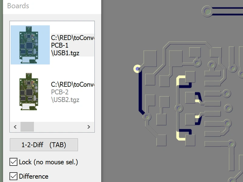
The complete 3D validation workflow is free, with no time limit. The STEP Export plugin adds STEP export and revision comparison, and you can try it free for 30 days.
The complete workflow, free forever
Load your files, see your board in 3D, find and measure anything, model special components and share secure 3D views.
Import your design files
Smart autoloader: Automatic stackup proposal
ZofzPCB automatically detects your file format and builds the complete layer stackup with little manual configuration. Drop in your Gerber, ODB++, or IPC-2581 files together with your BOM and netlist: the autoloader handles the rest. A manual stackup editor gives you full control over layer order, materials, and dielectric thicknesses.


Your complete board in 3D
A fully rendered 3D prototype: exactly as it comes back from assembly
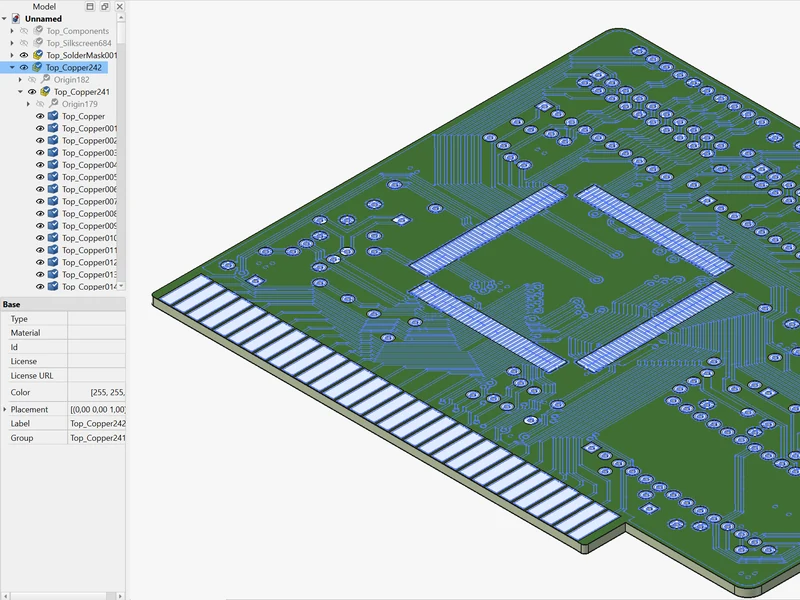
The moment you load your files, ZofzPCB renders your complete board in full 3D: every copper layer, every trace, every via, every net, and every component in its real position. This is your prototype, before a single board has been manufactured.
Rotate it, cut cross-sections, peel layers, strip components. Everything that is invisible in a 2D Gerber view or inside your CAD tool becomes visible here, before it costs you anything to find an error.


Build bespoke component models
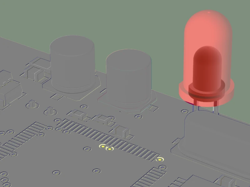
Full geometric control for components the auto-modeler can’t capture
The auto-modeler handles the vast majority of components instantly. For exotic parts, custom housings, or mechanical elements where exact 3D geometry matters, the Body Builder gives you precise control. Build the body from simple primitives with exact dimensions and colors; the pins come from the automatic modeler. The result becomes part of your project’s component library, reusable across all your boards. Critical for accurate STEP export and mechanical interference checks.

Navigate and inspect
Browse every component, net, pin, via and hole across all layers
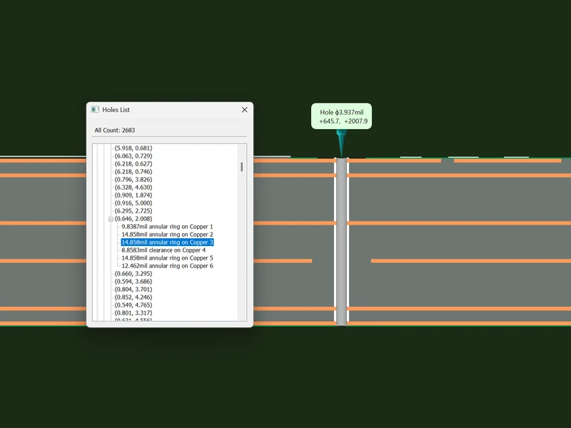
Click any component, net, or pin in the browser list and ZofzPCB instantly highlights it across every layer simultaneously. No searching, no guessing. The hole browser shows you clearances, annular ring dimensions, and a cut-through stack view for every via. Net highlighting lets you trace a signal through the entire board in 3D, invaluable for spotting routing errors that are invisible in a 2D view.


Measure with precision
Check critical dimensions and clearances on any layer
Pick any two objects (pad, hole, track edge, board edge), and ZofzPCB instantly shows the X, Y and XY distances between them. Verify pad-to-pad clearances and confirm track widths without leaving the 3D view. The Holes List shows the annular ring or clearance of every hole on every copper layer. Orthogonal camera mode gives you a true 1:1 scale view, so measurements read exactly as they would on the physical board. Layer and dielectric thicknesses come from the stackup editor.



Share a secure 3D view
Let others inspect your board without giving away your design data
Save your project in View-Only Mode and share an interactive 3D model with mechanical engineers, clients or manufacturing partners. Recipients open it in the free version of ZofzPCB: they can rotate, zoom and inspect the board, but cannot modify it, export it or extract manufacturing data.